Overview
This article reviews various SGMII (& 1000BASE-SX) concepts that are integral to our Private Island ® project and its soft Verilog MAC layer. We provide oscilloscope screen shots below to help illustrate the concepts.
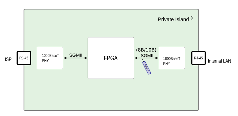
As shown in the block diagram below, Private Island utilizes a SERDES capable FPGA, such as the Intel Cyclone 10 GX on our company's Volitio™ board, to interface with SGMII Gigabit Ethernet PHYs and other SERDES-based peripherals.
Unlike a typical SoC, an FPGA is capable of asserting an external interrupt synchronous to specific packet transmit or receive events. The interrupt can also assert on specific octets / special codes within the Ethernet frame (i.e., end of packet). This interrupt flexibility is important for certain security functions and provides a reliable and predictable way to trigger our scope during debug of the SGMII / SERDES bus for both hardware and software debug.
For the oscilloscope screen shots provided in this article, the FPGA is configured as a transparent bridge between an Ethernet switch and an embedded Linux node. Certain received Ethernet frames from the LAN are mirrored onto a TAP port with the simultaneous assertion of an interrupt line. As shown in the image below, oscilloscope probes access the SGMII tap point via either AC coupling caps or via SMA TX connectors.
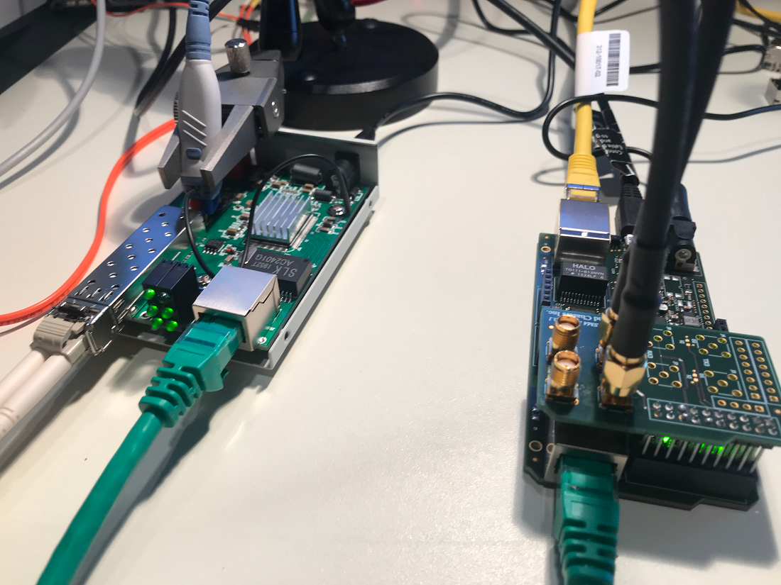
Note that the board on the left is a Gigabit Fiber Media Converter, and the board on the right is a prototype of a Priviate Island maker board.
Brief overview of popular PHY Interfaces
- GMII, which is specified by IEEE 802.3 defines a separate 8-bit bus for transmit and receive data plus several signals to convey additional information between the MAC and PHY. GMII is based on MII, which is defined in Clause 22. In addition to the data buses and control signals, GMII requires two 125 MHz bit clocks: GTX_CLK and RX_CLK
- RGMII, which was defined by HP, Broadcom, and Marvell, reduces the pin count primarily by utilizing double data rate signaling of the data buses and control, and this enables an SDR 8-bit data bus to be realized as a 4-bit DDR data bus.
- SGMII, which was defined by Cisco, utilizes two pairs of SERDES / LVDS differential buses to carry transmit and receive data at 1.25 Gbps. A differential receive clock is also defined but is optional and typically not used. Instead, the receive clock is recovered from the data on the differential pair. The data is encoded using an 8B/10B coding scheme, which is specified in clause 36 of 802.3. The effective bit rate is 8 / 10 * 1.25 Gbps = 1.0 Gbps, as you would expect. The out-of-band information conveyed by the GMII control signals (TX_EN, TX_ER, RX_ER, and RX_DV) are replaced by special code-groups (K values). This enables conveying information such as configuration, line state, and carrier events between the MAC and PHY.
SGMII Hardware Signaling
The SGMII specification provides its own definition of LVDS, which is derived from IEEE 1596.3-1996. However, the parameters provided in the SGMII specification are defined in the IEEE specification. For the purpose of SGMII hardware signaling, these two specifications are sufficient. PHY vendors often refer to this specification rather than providing their own numbers. Note that LVDS in general is an industry standard, and is defined in EIA/TIA-644A. A great resource for LVDS and differential signaling is the TI / National LVDS Owners Manual.
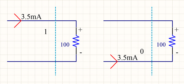
The figure below provides a very simple schematic of LVDS signaling. The concept being conveyed is that the transmitter drives a small current across a 100 ohm load in the receiver in one of two directions to produce either a positive or negative voltage across the receiver (Vod). This small current is superimposed over a common voltage (Vos), typically 1.2V. The industry standard LVDS specifies a 3.5 mA driver current. The SGMII specification implies it is less since |Vod| max is 400 mV. In practice, most SGMII drivers (e.g., PHYs) support the configuration of multiple drive levels.
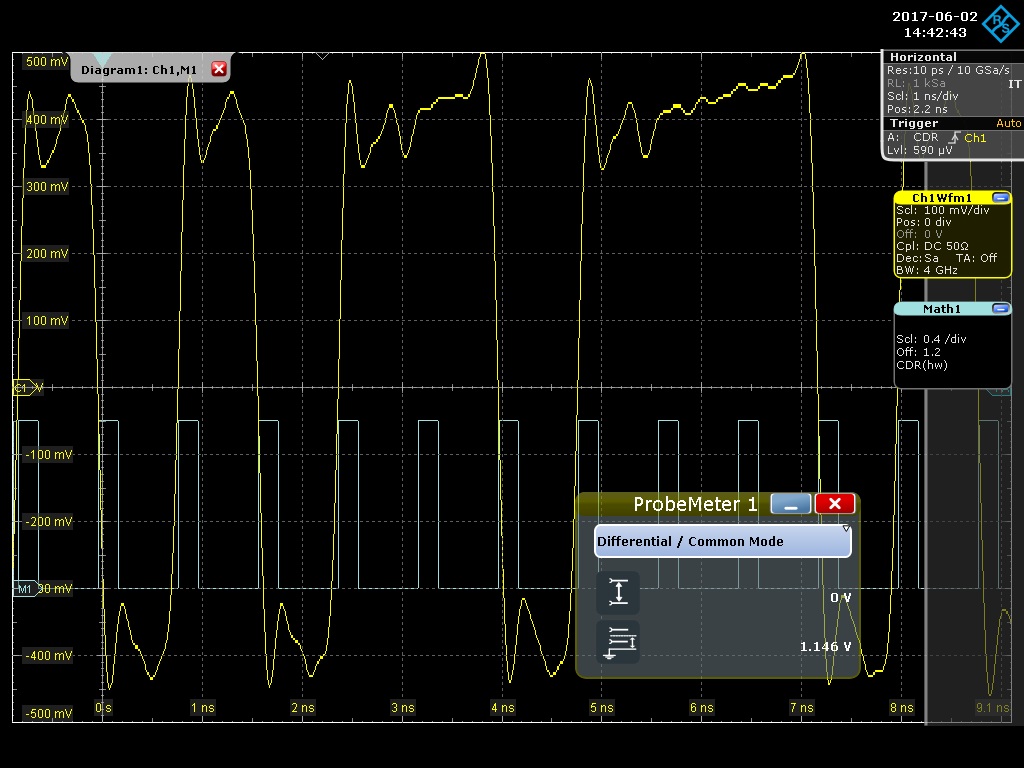
The next figure shows an oscilloscope screen shot of an SGMII bus using a 4.5 GHz differential probe. The probe tips are placed on the two AC coupling caps of the differential SGMII bus. The yellow signal is the SGMII signal, and the blue square wave is generated from the scope's HW CDR math function. A probe meter function is shown in the lower right. This is a feature / function of the probe and shows that the common mode voltage (Vos) is near 1.2V
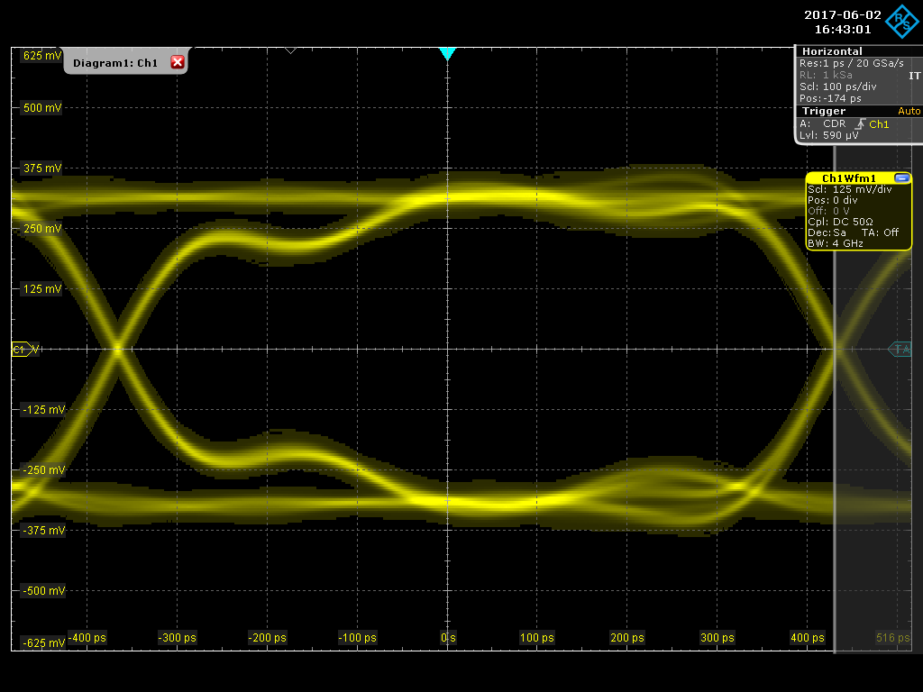
The next screen shot shows an SGMII eye diagram with 100 ms persistence enabled. As expected, the unit interval (UI) is approximately 800 ps. As can be seen in the upper right, the trigger is the built-in HW CDR.
A Look at SGMII Special Code Groups
Clause 36 of 802.3 defines certain 10-bit values as K values to convey non-data (out of band) information between the MAC and PHY. These K values take the place of the GMII control signals and special encodings of the GMII data bus. For Example, /K27.7/ defines a start of packet on the SGMII bus.
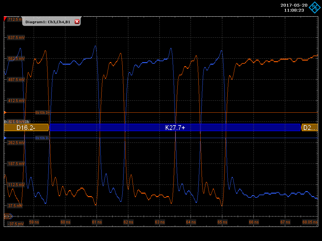
Referring to 802.3 Table 36-2 (valid special code-groups) and the screen shot below, we can see that K27.7 is defined as the bit sequence 001001 0111 ([a..j] with 'a' transmitted first). This screen shot was taken using two single ended SMA cables (see figure below) and utilizes the 8B/10B protocol decode function equipped with our scope. Note that that when the orange waveform is positive, the signal is a 1 and when the blue waveform is positive the signal is a 0.
The '+' after K27.7 indicates that the 10-bit waveform has a currently positive running disparity. Each code, both special and data, can either have a current positive or negative running disparity, and this indicates the difference of the total number of 1's and 0's on the wire. Refer to 802.3 clause 36.2 and Annex 36B for the details on running disparity and its rules.
Ordered Sets
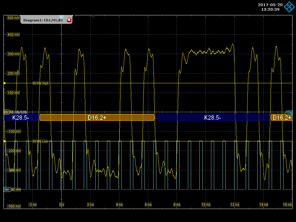
802.3 defines ordered sets (Table 36-3) that consist of one or more code groups, each of which starts with a special code group (K value). For example, /I2/ specifies the IDLE2 line state and is encoded by /K28.5/D16.2/. This waveform continually repeats while the line remains in a powered up idle state, and is shown in the figure below.
- K28.5-: 001111 1010
- D16.2+: 100100 0101
Data and Packets on an SGMII Bus
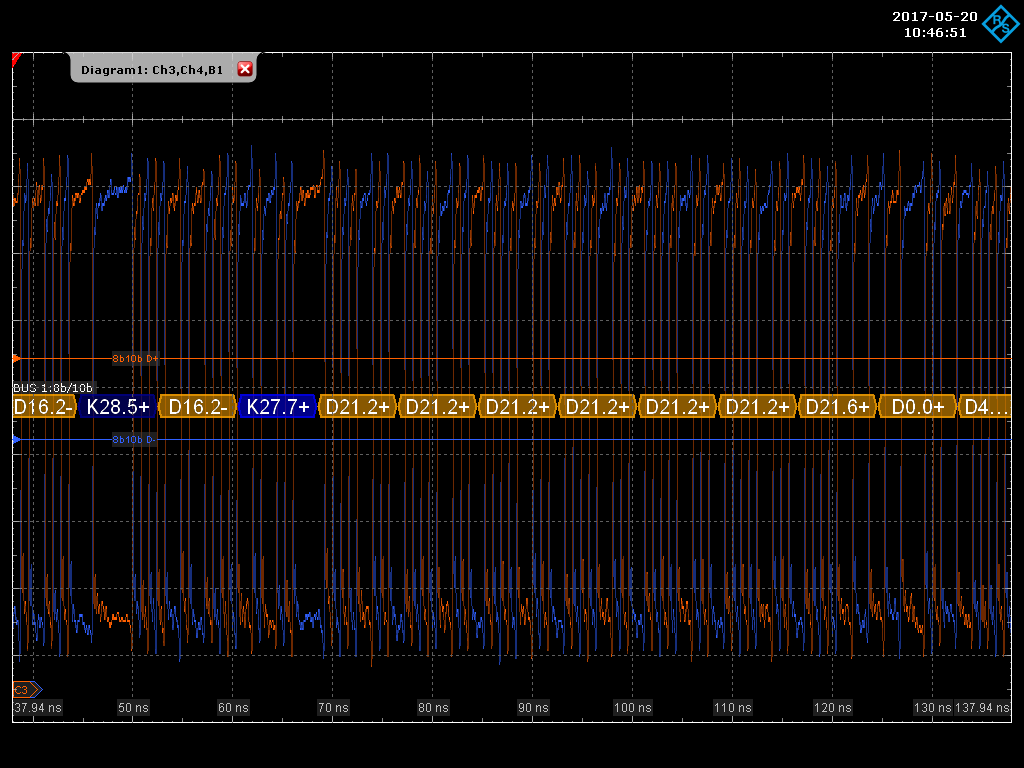
The next figure shows a captured packet preamble on an SGMII bus. Per 802.3 35.2.3.2.1 and 36.2.4.14, An /S/ code (start of packet delimiter, K27.7) replaces the first octet of the preamble followed by the remaining PREAMBLE/SFD sequence: 0x55 0x55 0x55 0x55 0x55 0x55 0xD5.
Note in the figure below that the special code groups (K) are shown in blue and the data code groups (D) are shown in yellow.
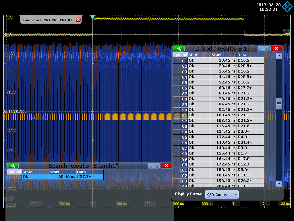
Our last scope screen shot shows a complete packet captured. The FPGA's interrupt line is used to trigger the scope synchronously with the reception of the packet on the TAP port. The scope trace highlights the functionality of the 8B/10B protocol decode feature, showing the full decode results in a table and a search result box looking for the K27.7 special code group, which appears on the SGMII bus 60.46 ns after the interrupt. This certainly gives new meaning to the term packet inspection.
1000BASE-SX
It's important to note that SGMII is derived from 1000BASE-SX, which is defined in 802.3 Section 3. 1000BASE-SX is a specification for Ethernet over Fiber, and it utilizes 8B/10B coding for out of band signaling.


