Overview
The Private Island ® open source FPGA networking project integrates an MDIO controller to offload a micro controller (µC) and enable real-time, parallel communication with Ethernet PHYs. Per IEEE 802.3-2018, clause 22, the FPGA performs Station Management (STA) via the two wire management bus, which consists of a clock (MDC) and a data signal (MDIO) (see 22.2.2.13 - 22.2.2.14).
This article discusses the architecture and design of the MDIO block. The project's source code is hosted here using cgit.
This article references the IEEE Standard 803.3-2018 for definitions and terminology. Note that this specification is available for free from IEEE via their GET Program, and the reader should refer to this standard and applicable Ethernet PHY data sheets for additional details.
The figure below shows the overall MDIO architecture within the FPGA. An external µC initiates FPGA MIDO reads and writes via the I2C interface (i2c.v). Complex sequences of multiple reads and writes can occur as programmed by the data image inside mdio_xx_data.v. The internal controller (controller.v) terminates the I2C communication and starts an MDIO work cycle by asserting a start signal, which is an input to the mdio_cont module. The MDIO controller in turn controls the MDIO driver (mdio.v) to perform MDIO communication with the Ethernet PHYs.
Additional low level details on the MDIO management bus are provided below in the MDIO Driver section.

MDIO Controller
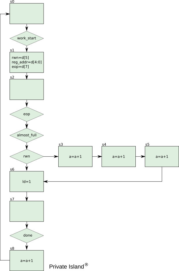
mdio_cont.v implements the MDIO controller state machine as shown in the figure below. It reads the data input d from the mdio_data module, which holds various MDIO sequence routines (e.g., extended addressing). Refer to the mdio_cont.v source for additional details.
MDIO Driver
The Management Data Input / Output (MDIO) bus is a two wire, out-of-band interface that connects the FPGA-based Ethernet MAC controllers to managed Ethernet PHYs. The purpose of the bus is configure, control, and obtain status of each PHY (e.g., status of auto negotiation and line rate).
The Ethernet PHY supported by the Darsena development board is the Texas Instruments DP83867. This device is considered the MDIO Manageable Device (MMD).
The MDIO interface is specified in 802.3-2018, clause 22 and is also referred to as the MII Management Interface (MIIM) or Serial Management Interface (SMI). The FPGA, which contains the MAC devices controlling the MDIO, can also be referred to as the Station Management Entity (SME).
An extension to MDIO is specified in IEEE 802.3-2018 clause 45. This extension provides additional device register space while retaining compatibility with the existing registers. The DP83867 supports this extended interface.
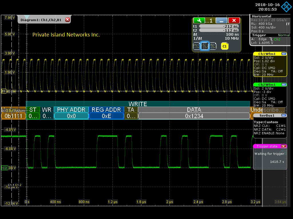
Scope traces are provided in the figures below and show the decode of the MDIO protocol for both read and write cycles. The data signal decode is listed in order below for a total of 32 clock cycles:
- Start Phase: 2'b01
- Read: 2'b10 or Write: 2'b01
- PHY Address: 5 bits
- Register Address: 5 bits
- Turn Around Phase: 2 bits
- Data phase: 16 bits
The MDIO data line is pulled high through a 2.2K resistor, so it returns to a logical high during idle periods. IEEE defines a preamble of a sequence of 1's at least 32 bits long, but clause 22.2.4.5.2 permits this requirement to be suppressed. Also the TI DP83867 supports preamble suppression.
The PHY address is 5 bits in length, which supports up to 32 PHYs on a single bus. However, the Private Island implementation assumes that each PHY is on its own MIDO data line and communicates with each PHY at address 0. The approach enables parallel communication with multiple PHYs and provides the opportunity for real-time scanning of the PHYs, which might be advantageous for certain security applications.
The MDIO clock (MCLK) is shared between the PHYs, and is currently clocked at 10 MHz. The maximum clock rate supported by the PHYs and the IEEE standard is 25 MHz.
MDIO Bus Scope Traces
Figure 3 shows a scope trace of an MDIO read cycle performed by the FPGA at register address 0x3 of the DP83867. This is a fixed PHY Identifier Register, and the PHY returns the expected 0xa231. The yellow signal trace is MDC, and the green signal trace is the MDIO data line.

Figure 4 shows a scope trace of an MDIO write cycle performed by the FPGA at register address 0xe. This is the DP83867 ADDAR register and is used to support extended addressing. The FPGA mdio_ti_data.v data image supports extended addressing write and read sequences via the I2C interface.
Additional Implementation Notes:
- When the MDIO signal is sourced by the PHY, it is sampled by the STA synchronously with respect to the rising edge of MDC.
- When the STA sources the MDIO signal, the STA shall provide a minimum of 10 ns of setup time and a minimum of 10 ns of hold time referenced to the rising edge of MDC
- Note that the TI PHY drives MDIO on the rising edge of the clock.
- Data is msbit first on the wire.
- TI DP83867 requires that the FPGA waits at least one MDC clock cycle after a hard reset is negated.


