Overview
We're in the process of porting the Private Island ® open source project for FPGA networking to the Intel Cyclone 10 GX. Prior to designing & building initial boards to support the project, we decided to build an FPGA Mezzanine Card (FMC) prototype for our Intel Cyclone 10 GX Dev Kit, and this brief article discusses the design.
Note that this article is a draft and a work in progress.
Intel Dev Kit for the Cyclone 10 GX
The figure below shows our FMC Expander prototype installed on our Intel Cyclone 10 GX Dev Kit system. The Dev Kit is a great resource, having two SFP+ cages, but it lacks some basic features for experimentation & development, such as GPIO header posts. Therefore, we decided to build a relatively simple FMC prototype to provide additional networking and various debug features so we could prove in certain concepts before building our own Cyclone 10 GX based design for Private Island.
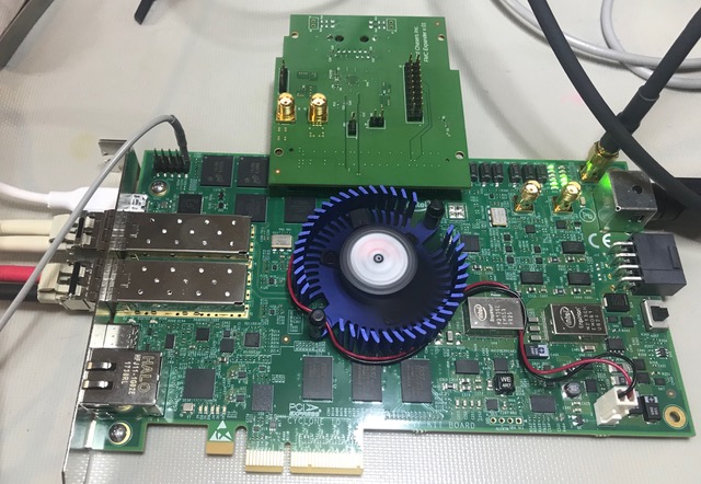
Information on the Cyclone 10 GX FPGA populated on the Intel Dev Kit is provided below:
- Device: 10CX220YF780E5G with 220K logic elements
- 20 nm process
- 12 transceivers supporting short-reach rates up to 12.5 Gigabits per second.
- Two SFP+ modules support 10GBASE-SR and 1000BASE-SX operation.
- Hard PCI Express IP blocks supporting up to Gen2 x4 applications
- 284 GPIOs with 118 pairs of LVDS (2*11848=284)
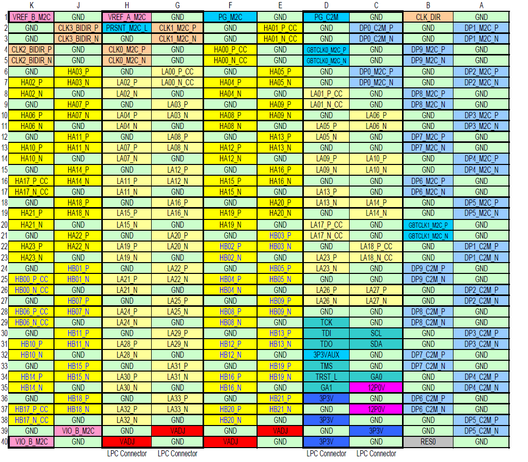
Note that the Intel Dev Kit is populated with a High Pin Count (HPC) FMC Connector (rows A through K) but only supports a subset of the total available signals. This is summarized below.
- A full set of differential pairs are routed to the LPC pins (rows C, D, G, and H) between the FPGA and mezzanine connector.
- Most of the HPC-only pins are no connects.
- DP0_C2M through DP4_C2M and DP0_M2C through DP4_M2C are supported on row A.
- By default, 1.8V is routed on the VIO_ADJ pins.
- 12V and 3.3V are supplied to the mezzanine connector.
The FMC pin assignments from VITA 57.1 are provided below. Additional information regarding FMC is provided in sections below, but please refer to the actual specification for details.
FMC Expander Version 0.1
The figure below shows version 0.1 of our FMC Expander. VITA defines the PCB side with the FMC connector as side one. This is also defined as the component side. The other side of the module is defined as side two, and this is the side that is accessible when working with the carrier and mezzanine (see previous figure).
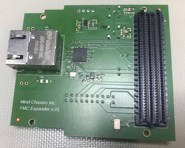
A summary of the FMC Expander features is provided below:
- 1000BASE-T SGMII PHY routed to Cyclone 10 GX transceiver. The PHY is a Texas Instruments DP83867
- A new Pulse Electronics PulseJack for verification purposes (older device shown).
- Dedicated GPIO header pins for easy probing of the DP83867 MDIO (J9) and PHY GPIO (J10) pins.
- Low jitter 125MHz, 1.8V LVDS clock oscillator (X1) to drive the GBTCLK0_M2C_P/N pair into the FPGA transceiver block as a reference clock.
- Twenty-pin header that supports various Cyclone I/O (both single-ended and differential).
- A pair of SMA connectors interfacing to a Cyclone LVDS I/O pair.
- Dedicated GPIO header (J6) for FPGA I2C debugging.
- A pair of Texas Instruments LDO regulators for generating 2.5V and 1.0V (PHY core voltage)
FMC Overview
FMC requirements are defined by the ANSI/VITA 57.1 standard. Listed below are some of the features and requirements of FMC related to our expander board:
- FMC defines ten multi-gigabit interfaces.
- FMC+ is a related standard, and its requirements are defined by the ANSI/VITA 57.4 standard. It defines 32 multi-gigabit interfaces
- FMC supports single ended and differential signaling up to 2 Gb/s; up to 10 Gb/s transmission with adaptively equalized I/O.
- The LPC connector (4x40) has 160 contacts and provides 68 user-defined, single-ended signals or 34 user-defined, differential pairs.
- The HPC connector has 400 contacts (10x40) and provides 160 user-defined, single-ended signals (or 80 user-defined, differential pairs), 10 serial transceiver pairs, and additional clocks.
- 4 differential clocks, 2 optionally sourced by the carrier
- All LA[] signals are on the LPC connector and Bank A.
- I2C Control Interface
- GA[0..1]: these signals provide geographical addresses of the module and are used for I2C channel select.
- Additional miscellaneous signals: JTAG, Present, and Power Good
- VREF_A_M2C This is the reference voltage associated with the signaling standard used by the bank A data pins, LAxx and HAxx. If the signaling standard on Bank A does not require a reference voltage, then this pin can be left unconnected.
- The single width FMC module has a width of 69 mm.
FMC Connector
The Intel Dev Kit uses a Samtec ASP-134486-01 (HPC) connector, and the Mind Chasers FMC Expander utilizes a Samtec ASP-134604-01, 10 mm LPC mate. VITA defines these as CC-HPC-10 and MC-LPC-10 respectively.
The figure below shows a bare mezzanine connector plugged into the Dev Kit carrier connector. It can be seen that only the LPC pins are loaded.
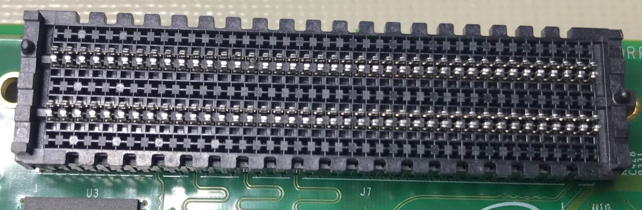
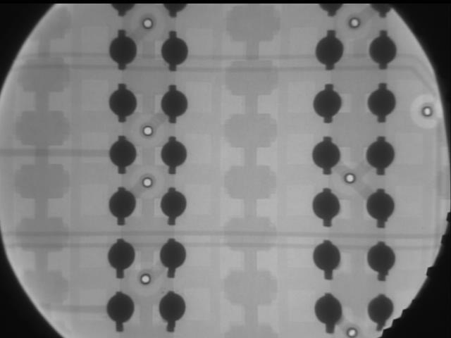
Samtec provides both a recommended PCB footprint and paste mask layer, and these were followed for this design. The reflow results were excellent as can be observed in the X-ray image provided below.
Summary
The FMC Expander appears to be fully functional and is proving to be a great resource for experimentation with the Cyclone 10 GX and also a platform for porting the Private Island project. We plan to continue updating this article with additional information on this design and FMC in general and anticipate designing additional FMC cards for high-performance applications.
Terms
- C2M: Carrier to Mezzanine
- FMC: FPGA Mezzanine Card
- HPC: High Pin Count Connector with 400 pins.
- LPC: Low Pin Count Connector with 160 pins
- M2C: Mezzanine to Carrier


