Overview
This article discusses and demonstrates the IEEE 802.3 10Gb Ethernet protocol for type 10GBASE-R and 64B/66B decoding using our company's Volitio™ board and a Keysight UXR3034A oscilloscope.
The Keysight UXR0334A is a 33GHz, 128 Gsa/s real-time oscilliscope. Some of its many features are listed below:
- 4 channels with 3.5 mm passive input connectors
- Inputs are 50 ohms +/- 5V max.
- 10-bit analog-to-digital converter (ADC)
- Powered by an Intel I5 @ 3.00GHz with 16.0 GB of RAM, running Windows 10 OS.
10GBASE-R is defined in clause 49 of IEEE 802.3. Some of its notable features are listed below:
- The 10GBASE-R PHY is the Ethernet-specific physical layer running at a 10.3125-Gbps data rate
- 64B/66B Control codes are listed in Table 49-1 of "Physical Coding Sublayer (PCS) for 64B/66B, type 10GBASE-R"
- The XGMII interface defines 32-bit data and 4-bit wide control character. These characters are clocked between the MAC/RS and the PCS at both the positive and negative edge (DDR) of a 156.25 MHz interface clock.
- The term 10GBASE-R refers to a specific family of Physical Layer implementations. The 10GBASE-R family of Physical Layer implementations based upon 64B/66B data coding method is composed of 10GBASE-SR, 10GBASE-LR, 10GBASE-ER, and 10GBASE-LRM.
- Blocks consist of 66 bits. The first two bits of a block are the synchronization header (sync header). Blocks are either data blocks or control blocks. The sync header is 01 for data blocks and 10 for control blocks.
- The remainder of the block contains the payload. The payload is scrambled and the sync header bypasses the scrambler. Therefore, the sync header is the only position in the block that always contains a transition. This feature of the code is used to obtain block synchronization.
- The encoding preserves the likelihood of detecting any single or multiple bit errors that may occur during transmission and reception of information. In addition, the synchronization headers of the code enable the receiver to achieve block alignment on the incoming PHY bit stream.
The image below shows the UXR scope next to the lab bench with the Volitio board under test. The SMA TX pair is connected to the scope with a pair of high bandwidth Sucoflex 102EA cables.

Volitio and UXR Setup
We configure our Volitio board to echo a real-time 10 GigE Ethernet stream onto a pair of SMA connectors. The Ethernet stream is sourced by a Windows 10 PC equipped with 10Gb SFP+ PCI-E NIC and a T1 Nexus 10G-SR SFP+ module. Keep in mind that the board is low cost FR4, and the Cyclone 10 GX FPGA transceiver has TX pre-emphasis disabled.
We connect the SMA TX_P to channel 1 and TX_N to channel 3. Note that this is just convention, and the UXR30334A does not utilize interleaving. We also connect a GPIO header post to channel 4, which we'll use later to set up an external trigger driven from the FPGA logic.
The first two screenshots show the 1) raw waveform & data eye and 2) the configuration of clock recovery using a second order PLL. This is necessary since a SERDES transmit pair embeds the data clock within the data stream, which is half the 10.3125-Gbps data rate
As can be seen below, the waveform exhibits quite a bit of distortion and this translates into an obviously faulty data eye.
Note that the screenshots shown below can be viewed at a higher resolution by clicking on them.


Our next step is to enable real-time Feed Forward Equalization (FFE) within the scope. Note that EDN has a nice article on the three methods of equalization supported by the UXR. The ability to auto set the taps and get good performance / equalization is certainly impressive.


Our next step is to set up 64B/66B decoding using Keysight's Ethernet 10GBASE-KR protocol decoder. We configure it to automatically descramble the stream; otherwise, the received bytes will not be recongizable to us.

Note in the screenshot below that the 01 synchronization pattern can be seen preceding the eight data bytes. Keep in mind that the data waveform is scrambled, but the synchronization bits and decoded bytes are not.

We can also choose to display the recoverd clock with the captured data (note that descrambling was disabled for this screenshot).

Next we enable an external trigger on channel 4. Although the Volitio platform supports the programming of complex triggers (via Python), the current trigger is just a simple assertion when the transmitted 8-bit control word changes. It may be helpful to point out that the FPGA fabric is being clocked at 156.25 MHz and is transmitting 64-bits into the transceiver during each clock cycle. Each 8-bit octet clocked into the transceiver has an associated control bit. For example, to send a continous /I/ (idle) pattern, only a simple behavioral Verilog block is needed, as is shown below:
// Transmit continous /I/
always@ ( posedge clk_156_25 or negedge rstn )
    if ( !rstn ) begin
        tx_data <= 64'd0;
        tx_control <= 8'h00;
    end
    else begin
        tx_data <= 64'h0707070707070707;
        tx_control <= 8'hff';
    end
In addition to easily identifying the beginning of our Ethernet packet, we can easily measure the delay through the Intel Cyclone 10 GX 10Gb transceiver.

The next screenshow shows the capture of a Link Layer Discovery Protocol (LLDP) packet

Impact of Scope Bandwidth on Capture and Decode of 10Gbps Waveform
It is trivial to adjust the bandwidth on the UXR30334A. The next three screenshots show the UXR's performance with the scope's bandwidth set at 16 GHz, 10GHz, and 5GHz. It was surprising to see data decoding still functioning at 5GHz. Also note that setting the bandwidth below 5GHz resulted in just a waveform of noise (as was expected).


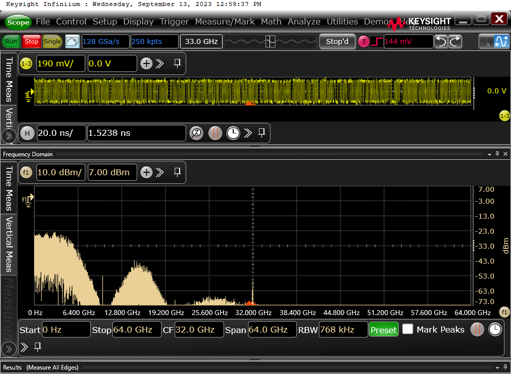
Our last screenshot shows the results of an FFT with the scope operating at full bandwidth (33GHz).
In summary, the UXR30334A is an amazing scope and is both simple and intuitive to use. Also, the 10GBASE-KR decode package enables advanced debugging and understanding of the IEEE 802.3 64B/66B encoding.


